DI/LDI & AOI Automation QRI


Highlights
- With a cycle time of 13 sec incl. 3 sec table change time, capacities of > 4 PCBs/min. – both sides processed – is possible Prepared for MES (OPC/UA) connection
- Automatic override setting according to PCBs weight (process safety)*
- Handling up to 6kg PCBs
- 100% traceability via log-fi le & database
- Contact-free centering via CCD cameras (very high positioning accuracy)
- No scratching of the PCB surface
- Variable offsets (X, Y & R axis) can be set for all robot positions (pick & place) in automatic mode
- Placing position on LDI / AOI table can be configured by +/- 90 ° or 180 ° turning(may lead to cycle time savings for the process machine)
- The automation reacts status-oriented. Example: If a printed PCB is lost or an LDI / AOI malfunctions with subsequent inital reset, the automation automatically recognizes the new situation. Production can continue seamlessly
- Existing operating modes:
- LDI / AOI1 A side
- LDI / AOI2 A side
- LDI / AOI1 A / B side LDI / AOI2 A / B side
- LDI / AOI1 A side & LDI / AOI2 B side
- LDI / AOI1 A side & LDI / AOI2 A side
- Logfi le creation:
- Alarm history
- Event
- Interface M2M
- Offset placing of OK boards individually adjustable via HMI
- Simple manual intervention, without interruption of the running automatic mode
- Database connection (read & write)*
- Automatic gripper adjustment incl. format check without cycle time loss
- Order data collection via DMC * on the PCB or via job list
- Automatic dummy panel Recognition (job separator panel )*
- Certifi ed ESD version*
- Control of processes via weight and thickness information*
- Automatic cleaning of each side before processing via noncontact cleaning solutions
Description
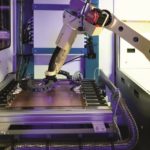
The system is designed for the automatic linking of 2 process machines. The PCBs are tranferred inline from the preprocesses to the non-contact camera alignment via a transport system. Accurate, if neccessary touching only in the edge area, they are placed on the process machine via a reliable gripper system with individual ejectors for each suction cup. After the fi rst side has been processed, transferring the PCB from robot 2 to robot 3 results in fl ipping, so that the second side of the PCB can be processed on the second process machine. The fi nished processed PCB is then transferred by the 4. robot to an outfeed conveyor and fed to the subsequent inline process.
Basically, the automation acts as the master for the process. Order data are transfered for each individual PCB to the process machine from the PCB coding or by input into the HMI – manually or via bar code readers. This speeds up the data preparation and the automation can automatically adapt to the different board conditions (size, weight, order change) if necessary. NOK PCBs can be stored in a separate cassette. If required, the system can also be designed as a stand-alone version for loading and unloading via L-rack, horizontal boxes or for use in the Soldermask area via slot cassettes.

Klicken Sie auf den unteren Button, um den Inhalt von customer-181znpukyiq9repm.cloudflarestream.com zu laden.